Canvas
The center canvas is where you draw joints, members, supports, and loads. Pan and zoom while checking whether members connect at the intended nodes and whether load arrows point in the expected direction.
This guide explains the full NextForm workflow: create nodes and members, assign section properties, choose support restraints, apply node and member loads, organize load cases and combinations, solve the frame, and interpret reactions, axial force, shear force, bending moment, and displacement results.
The workspace combines a visual frame canvas with editable tables, so you can draw the analytical model and still control exact coordinates, member properties, support restraints, and load magnitudes.
The center canvas is where you draw joints, members, supports, and loads. Pan and zoom while checking whether members connect at the intended nodes and whether load arrows point in the expected direction.
The bottom panel holds tables for nodes, materials, members, dimensions, supports, loads, and load combinations. Use it for exact coordinates, material values, release settings, load factors, and ordered review of model data.
The right panel shows the selected node, member, support, or load so you can edit the item that is visible on the canvas without hunting through the full table.
After solving, the results area lists support reactions and member end forces for the active load case, while the result buttons switch between model, axial, shear, moment, and displacement diagrams.
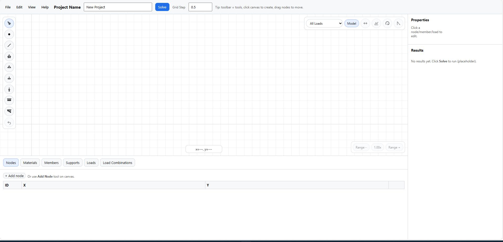
The main workspace shows the complete modelling loop: menus for file actions, toolbar tools for geometry and loads, a canvas for the frame, properties for selected items, and tabs for precise data entry.
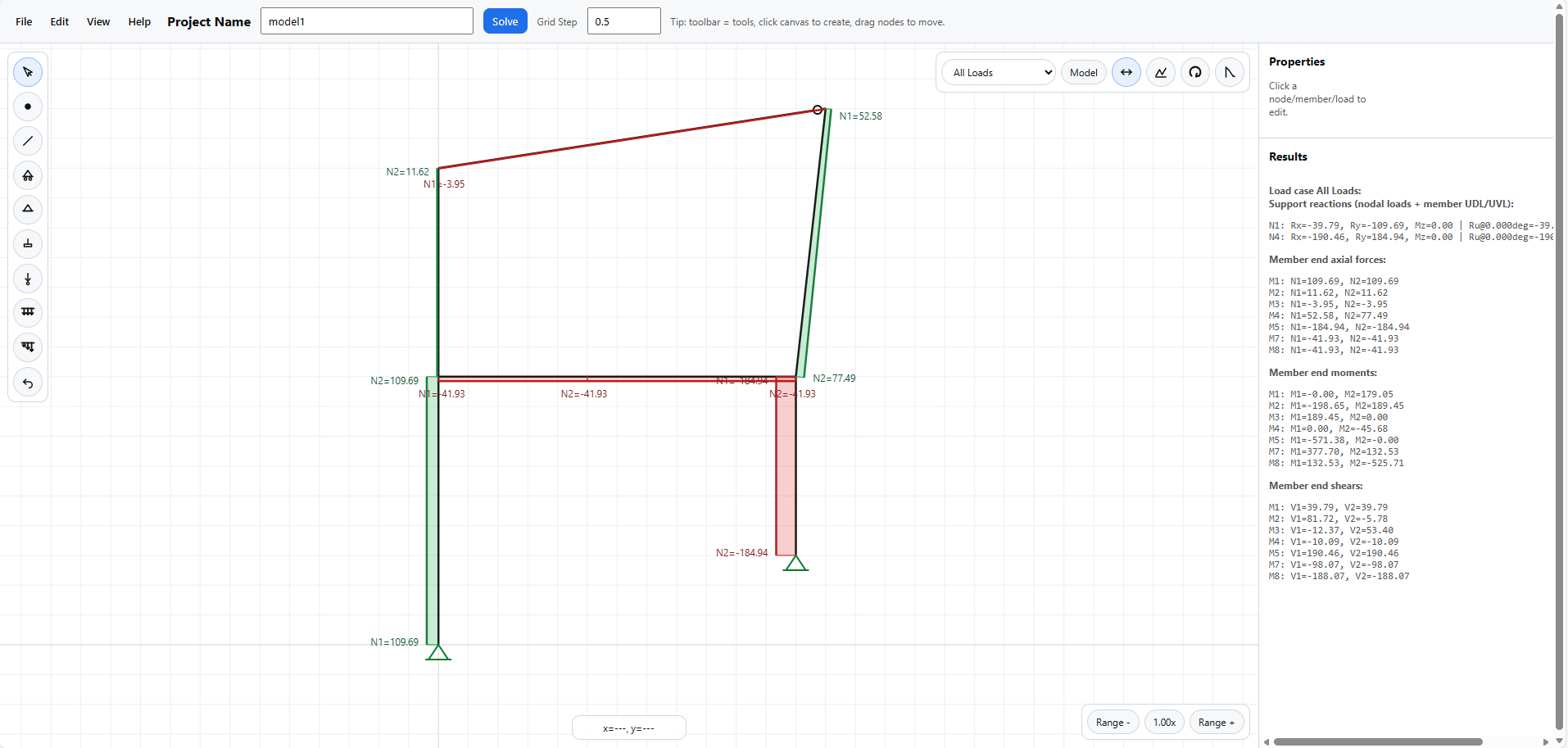
After solving, the model view displays reaction labels, member result labels, and the right-side summary for checking equilibrium and member-end forces.
The left vertical toolbar is for direct canvas modelling: place joints, connect members, add supports, and apply repeated node or member loads without opening the tables first.
Returns the canvas to selection mode. Use this when you want to click items, inspect labels, or edit properties.
Places a node on the canvas. If you create a node on or near an existing member, the app can split that member at the new point.
Click a start node and then an end node to create a member between them. Preview lines help confirm the connection before it is placed.
The roller, pinned, and fixed support buttons place supports directly on nodes. After selection, support restraints and angle can still be edited from the properties panel or Supports tab.
Opens a popup first so you can define a new node load or reuse an existing one. After pressing Add, keep clicking nodes to apply that same load repeatedly.
Opens a popup for direction and magnitude, or lets you choose an existing member UDL. Then click one or many members on the canvas to apply the same grouped load.
Works like the UDL tool, but asks for `w1` and `w2` so the load can vary along the member.
Use this after accidentally placing a node, member, support, or load while working directly on the canvas.
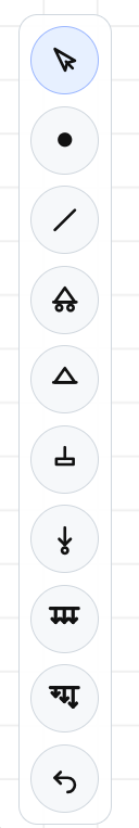
Use these tools when you want to build the frame visually, then confirm exact values later in the bottom tables or properties panel.
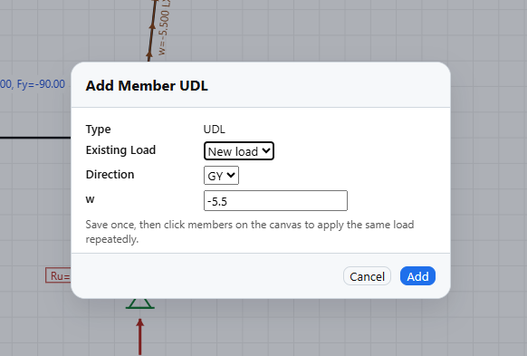
Load tools open a popup first so one load definition can be applied to several nodes or members, keeping repeated wind, gravity, or test loads consistent.
Create nodes from coordinates, edit positions numerically, and review node IDs.
Define reusable section properties such as area, inertia, elastic modulus, capacities, and self-weight.
Assign node connections, material links, releases, section properties, and split members at a chosen distance.
Review or edit dimension annotations already placed in the model.
Edit support restraints, angle, and presets in a table format.
Manage grouped node loads and member loads, descriptions, directions, magnitudes, sorting, and manual ordering.
Create load cases, assign loads to them, set load factors and combination factors, reuse description bundles, and manage self-weight bundles.
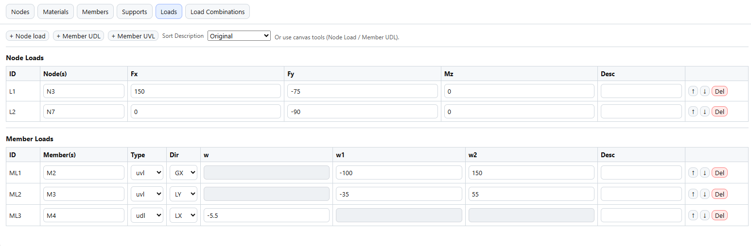
The Loads tab is where you edit grouped node loads and member loads by ID, member reference, direction, magnitude, category, and order.
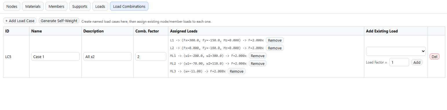
Here you can create named cases, assign loads, and manage both load factors and combination factors.
Whenever you click something on the model, the right panel becomes the focused editor for that item and shows only the fields relevant to the selected object.
Edit coordinates, connectivity, length, releases, material assignment, and member properties.
Edit restraints, angles, node forces, nodal moments, member load direction, UDL and UVL values, descriptions, and delete actions.
The virtual All Loads selector is not a saved load combination. It solves every node load and member load in the model at `1x` factor so you can inspect the combined unfactored response.
Make sure the frame has enough translational and rotational restraint, connected members, valid material properties, and load directions that match your intended axes. If the model is unstable, the app will warn you.
Use the case selector above the canvas to switch between `All Loads` and saved load cases. Then compare the model, axial, shear, moment, and displacement views to confirm the force path and deformed shape.
Esc cancels the active tool. Delete removes the selected item. Ctrl+Z undoes the last change.
Use the mouse wheel to zoom. Drag empty canvas space to pan. Use Centralize from the View menu if you want to refit the model.
This app is an engineering aid. Results should always be checked independently and reviewed by a competent person before being used for design, construction, or safety-critical decisions.